Fred Locke
Multipart Porcelain Insulators
(page 3 of 6)
Go to Main Page
Go to Multipart History Page 1 Page 2 Page 3 Page 4 Page 5 Page 6
Click on the links below to view each style:
M-2795 (Locke catalog #316)
Production date: 1900-??
The following was taken from Elton Gish's book, Multipart Porcelain Insulators. The book has many more historic photos of M-2795 in service and information about the northern California lines.
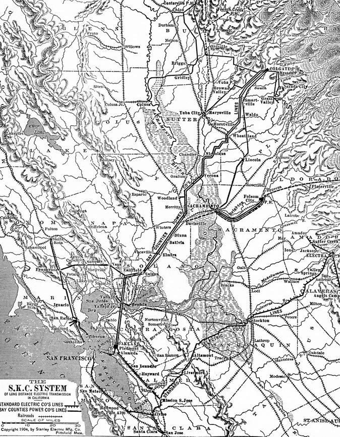
Bay Counties Power Co. and Standard Electric Co.
Suddenly a market for hydroelectric power developed just as de Sabla had envisioned. The Oakland Transit Co. was seeking cheaper electric power. A new company, the Bay Counties Power Co., was organized on June 4, 1900, to consolidate the ownership of the Nevada County Electric Power Co. and the Yuba Electric Power Co. Two
companies, the Bay Counties Power Co and the Standard Electric Co., worked together planning two 40,000 to 60,000 volt power lines, which would be used to transmit electric power from hydroelectric plants in northern California, to Oakland, San Francisco, and the surrounding area. The Bay Counties line would be a double circuit from Colgate to Oakland, a distance of 152-miles, and on to San Francisco by way of the Standard Electric Co. line, for a total of 222 miles. The Standard Electric line would run from Electra on the Mokelumne River to Oakland and San Francisco, a distance of 219 miles.
This story began with Paris-born Prince Andre Poniatowski, who came to America in 1892 and again in 1893, seeking investments on behalf of European bankers. His great-great grandfather was the brother of the last king of Poland, and his uncle Count Walewski was the illegitimate son of Napoleon. He grew up in the atmosphere of the court of Napoleon III, winning two duels, serving in the French cavalry, and developing a passion for horse-racing, yachting and big game hunting. After marrying the daughter of the San Francisco banker, William H. Crocker, in 1893, the Prince became interested in California mining interests and organized the California Exploration Co. Soon he became interested in the problem of how to supply cheap electrical power to the mines and funded the construction of a small hydroelectric plant on the Mokelumne River for the Blue Lakes Water Co. The success of this project got the Prince thinking of bigger dreams. No office-chair promoter, he spent two weeks braving the hardships of frigid high-mountain elevations and rough trails gathering engineering data in the Blue Lakes region. From this data, he calculated water storage capacity, size of dams required, and estimates of cost for a much larger hydroelectric project that would generate upwards of 20,000 kilowatts. He dreamed of a plant that could serve San Francisco 219 miles away. Recalling the event, the Prince said, "But the next day the engineers told me that the longest electric power line did not exceed 130 miles; that the 40,000 volts necessary for operation at a greater distance had never yet been attempted on any line."
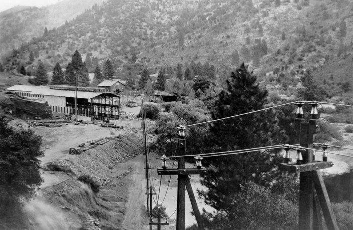
Power line leaving the Electra Powerhouse of the Standard Electric Co. Note the Fred Locke M-2795's with porcelain pin sleeves.
Photo is from the June 1904 issue of Electrical Age. (Courtesy of Bob Stahr)
In pursuit of his dream, Prince Poniatowski and other investors formed the Standard Electric Co on November 27, 1897. The Prince approached the three major electrical manufacturing companies, General Electric, Westinghouse, and the Stanley Electric Co. to bid on the project and to provide insulator designs for 40,000 volts. All three companies declined, stating that no insulator had yet been made that would be practical above 30,000 volts and that no insulator could be made that would hold up to the required 40,000 volts, which was necessary for this project to be economical. However, work proceeded on the design of a power plant at Electra and on the power line. Dr. Frederick A. C. Perrine, first professor of electrical engineering at Stanford University, was the chief engineer. One of his associates was Frank G. Baum (see Baum patent No. 838,163 for M-4415A with corrugated top skirt).
The original plan had been to route the transmission lines across the shallow southern arm of San Pablo Bay on steel towers, but federal navigation authorities refused permission. Consequently, the line was run from Electra to Mission San Jose, where one branch was built to Oakland and a second around the lower end of the bay and north to San Francisco. The Bay Counties lines would have to cross the Straits of Carquinez (connecting San Pablo and Suisun bays) on the eastern side of San Pablo Bay, which was a span of nearly 4300 feet between the towers, with 4448 feet of cable sagging down to within 289 feet of the water. Previously, the longest span was 1,576 feet in British Columbia. Special steel towers and insulators were designed to withstand the strain of the long span, which were needed to gain permission from the federal navigation authorities. The long span used stranded steel cable, but most of the transmission lines used 37-strand aluminum cable instead of copper. The Prince declared that he saved $200,000 in the cost of the transmission line by using the aluminum cable.
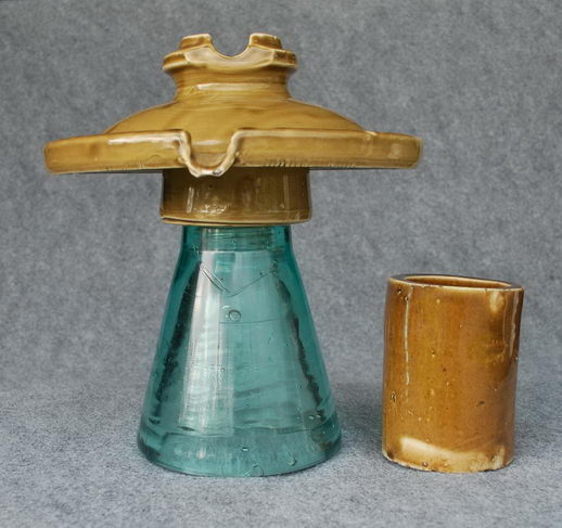
The four cables on the steel towers used for the Carquinez crossing were supported by huge porcelain insulators specially designed and manufactured by Fred Locke. A group of six of the special insulators, called “saddle insulators” supported the weight of each cable draped across the cast iron saddle mounted to a wooden platform composed of heavy timbers. The wooden platform had six large holes drilled to fit securely over each of the six insulators. The cast iron saddle contained five grooved steel sleeves set in line on which the cable rests and allows for any movement due to expansion and contraction. The cable was 19-strand galvanized steel 7/8” in diameter. The immense porcelain saddle insulators were 18 inches in diameter, 11 inches tall, weighed 45 pounds, and were mounted on huge solid conical-shaped steel pins. The insulators were made of three glazed porcelain shells each with flared skirts and cemented together with sulfur cement. A long conical porcelain sleeve was slipped over huge steel pin under the saddle insulator. The skirt of the inner shell of the 3-part insulator extended down below the bottom of the insulator and out around the top of the porcelain sleeve. The Fred Locke design to support the saddle survived until about the late 1930’s when it was replaced with the “pyramid” design composed of six strings of pedestal-type insulators angled in a pyramid shape to the saddle. Each of the strings consisted of three pedestal insulators bolted together. This configuration and the old steel towers were replaced in 1998 at a cost of $4.7 million. The new steel towers are 394 feet tall which dwarfed the old towers. Each of the new towers is assembled with 31,000 bolts.
Carquinez crossing
John Martin, Fred Locke's selling agent in California, and Eugene de Sabla, Jr. were working with the Bay Counties Power Co. to build two 40,000 volt parallel lines from Colgate on the Yuba River (28 miles northeast of Marysville) to Oakland. The Prince and John Martin were collaborating together to find an appropriate insulator design that would be suitable for both lines. Through his close association with Fred Locke, John Martin discussed the problem with him, explaining their requirements for a high voltage insulator. After obtaining assurances from Fred Locke that he would be willing to tackle the problem, Mr. Martin then approached the Stanley Electric Co to set up a meeting.
Very early in 1900, the Martin engineers and Prince Poniatowski asked Fred Locke to join them at the office of the Stanley Electric Co. in Pittsfield, MA. They met with C. C. Chesney (see patent No. 761,760 for lily-shell multipart insulator) and a young assistant who had been working on a design for large capacity insulators. This young assistant was Richard H. Sterling. On March 14, 1900, Richard H. Sterling of the Stanley Electric Co. applied for a patent for an insulator with an eave-trough (gutter) around the flattened top skirt and a detachable spout. On December 18, 1900, patent No. 664,301 was granted to Sterling for his invention. This was the design proposed by the Stanley Electric Co. The Sterling patent sought to reduce the chance of electrical arcing during rainy weather, where it was thought that the electrical current would follow the water dripping from the edge of the insulator, and thus more easily arc to the pin. By providing the eave-trough to collect the rain water, and a spout to direct the water away from the pin, it was hoped that the chance of arcing would be reduced. The detachable spout would direct the water even further away from the pin. They thought, too, that the electrically charged water would be attracted to the pin. Just the opposite was experienced. Photographs of M-2795 in the July 1901 issue of the Journal of Electricity, Power & Gas showed the insulators being tested under conditions of simulated rain. Water dropped normally from the spout when no current was applied. At 40,000 volts the water was repelled away from the pin and fell in a scattered pattern.
Based on his experiments at Cornell University in 1896 (see book, Fred M. Locke: A Biography), Fred Locke suggested at the meeting that the insulator be made with a glass bottom skirt to prevent electrical puncture and a porcelain top skirt, which would better resist the wetting effects of rain and fog. A spout would be formed in the porcelain top skirt for simplicity rather than using Sterling's detachable metal spout. All agreed to the final insulator design. According to the book P. G. & E. of California, by Charles M. Coleman, after considerable negotiations, Fred Locke "agreed to undertake the job, subject to an indemnity in case of failure, and a firm order of $30,000 in case of success". However, Fred Locke lacked the capital necessary to build the two kilns needed to produce the order. John Martin was very anxious to furnish the 100,000 insulators for both projects, particularly, since he had a vested interest in the Bay Counties project, and he was Fred Locke's west coast selling agent. He agreed to advance Fred Locke the money for the new kilns and testing room.
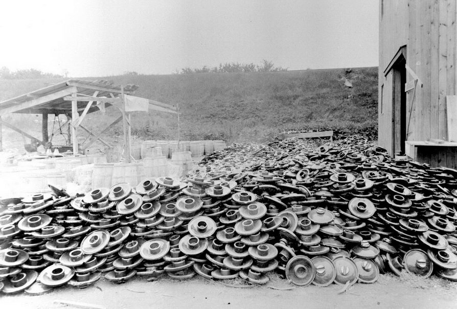
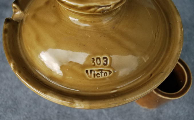
A pile of tops for M-2795's at Fred Locke's Victor, NY factory in the summer of 1900. The tops have the "303" marking.
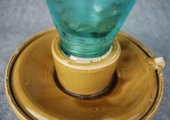
When Fred Locke returned to Victor, he quickly began working on plans for the two kilns, and a new two-story wooden building for the testing room. He also worked out the details of the final design for M-2795, which he later cataloged as No. 316. The original catalog number before development of the "Victor" insulator styles was "303". The bottom glass skirts were ordered from the Brookfield Glass Co. The porcelain top skirt consisted of two pieces of porcelain glaze-welded together. A porcelain ring was made separately and glaze-welded under the top skirt. The crown with cable groove formed in it was made separately and attached by hand to the top skirt much the same way as a handle is applied to a tea cup - the mating surfaces are wetted, pressed together, and the seam smoothed with a wet finger or cloth. The glass bottom skirt was cemented into the porcelain ring by means of a mixture of equal parts of sulfur and sharp sand. The porcelain top skirt was 10-1/2 inches in diameter, and the completed insulator was 11-1/2 inches tall. The booklet, The Locke Story, published in 1947 by the Locke Insulator Mfg. Corp., said that the insulators sold for $1.00 each; however, catalog No. 5 (1900) and a 1901 Western Electric catalog, both showed the price at $1.75. In either case, this was a rather large sum when considering that about 100,000 insulators were used by the two companies. Two months after the meeting in the offices of the Stanley Electric Co., Prince Poniatowski traveled to Victor to witness the successful testing of M-2795.
An interesting description of M-2795 can be found in the August 1901 issue of the Journal of Electricity, Power & Gas:
"Without tiring you with details of the development of the insulator that the Standard Electric Company is using, I will state briefly that at the time we adopted it there was nothing on the market that would anywhere near meet our requirements, hence it was not until after many months of cut and try methods had passed before we obtained an insulator that would stand the
exacting test to which it would be subjected. [The illustration] shows the Standard insulator in section and perspective. It is what is called a two-part insulator, the upper part being of porcelain and the lower part of glass."
"There are several reasons why a combination insulator was decided upon. First, the dielectric strength of the glass is greater than an equal thickness of porcelain; while, on the other hand, moisture clings less readily to the porcelain. It was also found that a much cheaper insulator could be made in this way than making it either wholly of glass or of porcelain. As a matter of fact, the insulator as designed could not be made of glass in one piece. The two parts of the insulator are cemented together with a cement composed of a mixture of sulfur and sharp sand in about equal parts. After being cemented together, every insulator is subjected to a test of 120,000 volts for a period of five minutes, and if any insulator shows sign of weakness, it is rejected. Thirty insulators are place on the testing rack at one time. If an insulator gives away, it is replaced with another one, and the pressure is applied again. This process is repeated until the nest of insulators stands the test for five minutes. This method of testing is very rapid, as two men will test thirty insulators in about fifteen minutes."
"On the base of the pin is used a porcelain sleeve 5 inches long, which rests upon the crossarm and projects up beneath the glass petticoat. The object of this porcelain sleeve is to protect the pin in the event of an arc tending to strike from the eave on the insulator to the base of the pin. It also protects the pin from weathering."
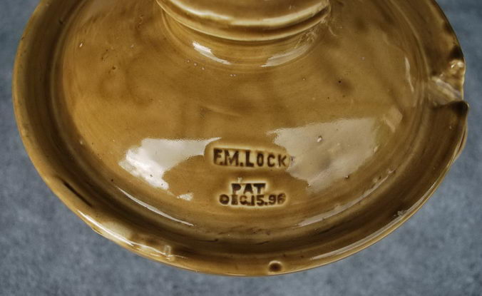
Fred Locke was making M-2795 based on the Sterling design for the porcelain top. However, it was Fred Locke's idea to mold the spout into the body of the top skirt rather than using Sterling's detachable spout, and it was his idea, too, to use the glass bottom skirt. He knew that Sterling had applied for a patent covering the invention of the eave-trough and detachable spout, but he wanted to lay claim to the final design. By declaring the design to be his own, he would gain much needed publicity from the success of these two world famous hydroelectric projects. There was one door open to him. On April 26, 1900, Fred Locke applied for a design patent to cover the final shape of the porcelain top skirt. This design was identical to Sterling's letters patent except it called for the spout to be made by turning down a portion of the eave-trough. The design patent granted Fred Locke exclusive rights to the final shape of the porcelain top skirt, and it was a bold way to lay claim to Sterling's eave-trough and spout design. Fred Locke was granted design patent No. 32,741 on May 29, 1900. He was so proud of this design patent that he included the patent date in a new marking stamp that had six patent dates.
M-2795 was the basis for the "Victor" designs that were various combinations of porcelain top skirt with either an eave-trough with one or two spouts or no eave trough, and either a glass or porcelain bottom skirt. In the November 1901 issue of the Journal of Electricity, Power & Gas, Fred Locke claimed full credit for the eave-trough and spout design. He implied in the article that he had developed the eave-trough and spout design shortly after introducing U-937 in
1896. He started out by saying:
"Exhaustive experiments were then carried on with a view of ascertaining the best means of carrying water off from the outer top surface of insulators wet from rainfall, etc. As a result the eave-trough type was developed. Three of these designs are shown [article included illustrations of U-937, M-2336 and M-2795]."
Fred Locke continued by giving his theory behind the design of M-2795:
"Now, it will be noted that up to this point the idea is dominant that the more surface embodied in the petticoats between the pin and line the better the insulators produced. But with the higher potentials, it was found that we were contending against insidious surface leakage, and thus by interposing large surfaces in the shape of petticoats in order to insulate, we presented the greatest detriment to efficient insulation. It will readily be seen that were we able to design an insulator with no surface whatsoever, and just distance between wire and pin enough to prevent arcing at potential used, we would have a perfect insulator. Consequently, if we designed insulators with the required arcing distance, and with just as small a surface as possible, we then have as perfect an insulator as is possible under present usage."
"In general, then, we may state that our best designs embody the maximum arcing distance that is possible with a minimum amount of surface, over which static discharge may take place, such insulators to be made of a material having the most favorable hygroscopic properties and the greatest surface resistance and mechanical strength. This material is porcelain, as technically developed."
"In the "Victor" designs all of the above features are embodied. To obtain the proper arcing distance, the top is extended laterally, or in an umbrella shape, and the center is extended down around the support, also preventing arcing to the pin. All other surface [petticoats] is cut out."
In conclusion, Fred Locke wanted everyone to know that the M-2795 design was wholly his:
"I wish to say, in closing, that I desire it clearly understood that the eave-trough insulators, of the design...used by the Bay Counties Power Company and the Standard Electric Company of California, are wholly of my designs and patents. The large saddle and strain insulators used in the great Carquinez span of the Bay Counties Power Company, although made by me, were wholly designed by Mr. R. H. Sterling, superintendent of the Bay Counties Power Company."
In the January 1902 issue of the Journal of Electricity, Power & Gas, the editors printed the following correction in response to Fred Locke's claims in the previous issue that he alone designed M-2795:
"...that the eaves-trough insulators...are wholly Locke's designs and patents...is a palpable error...for patent No.
664,301 was issued to Richard H. Sterling upon a form...appears to be identical with the insulator which the Standard and Bay Counties companies are using today. This patent is now owned by the Stanley Electric Manufacturing Company, of Pittsfield, Mass., and publication of the evident inadvertence in which credit is claimed for the "designs and patents" upon which the eave-trough insulator is established, works a regretted injustice to Mr. Sterling as
well as, furthermore, a serious injury to the Stanley Company."
M-2795 was satisfactory under arid conditions, but the margin of safety was exceeded during wet conditions. The top skirt acted as a flat pan that easily collected dirt. In the 1903 Journal of AIEE, an article titled, "Bay Counties System", described the problems with dirt accumulating on M-2795: "The only place where we had trouble with the accumulation of dirt on insulators was near salt water and cement works. Rain is Heaven's own blessing...it cleans the insulators and stops a good deal of the damage to wooden supports [pins]. This is true of salt water districts especially. The first few drops that fall after a prolonged dry spell causes a good deal of a display which soon passes however and all is quieter and better than it was before."
The wooden pins for M-2795 were made from eucalyptus wood that was quite common in California. The wood was cut in three-inch blocks and boiled in water for 24 hours to remove the sap. After air drying for several months, the blocks were then boiled in linseed oil for several hours to produce a moisture-proof finish. The finished pin was 16-7/8 inches long with 1-1/2 inch threads on one end.
The burning of the eucalyptus wood pins was a constant problem near fog prone areas. Some of the wooden pins were soon changed out with a pin made from steel gas pipe, which had lead threads molded on the tapered end. Another solution was patented by Fred Locke. His patent No. 698,976, dated April 29, 1902, claimed the use of a porcelain sleeve around the pin. M-2795 was fitted with a five-inch porcelain sleeve that rested on the crossarm and extended up inside the glass bottom skirt. The object of this porcelain sleeve was to protect the pin in the event of an arc that might strike from the edge of the glass skirt to the base of the pin, and it also protected the pin from weathering. Bill Rohde discovered that he has one of these porcelain sleeves in his collection. He did not know what it was until one day we were discussing the problem of M-2795 pins being burned and the use of these simple porcelain sleeves. No other specimens have been reported.
Another interesting problem was observed along salt water fog areas and reported in the 1904 issue of the Journal of AIEE. In the article titled, "High-Tension Insulators", by V. G. Converse, R. S. Hutton reported the problem with M-2795: "The separate parts of the first ones used, were put together with sulfur, and we had some field fires that we were not able to account for. We afterwards found out that it was due to the fact that the leakage heated the insulator to such an extent that the sulfur was set on fire, and as it dropped down, set the grass on fire around the poles." In March 1904, the insulators in these salt fog prone areas were replaced with M-4384 mounted on iron pins, and the line voltage was increased from 40,000 volts to 55,000 volts. A few specimens of M-4384 have been located in California, and three of them have the #7-1 marking. It has been reported that some of the M-2795's that were removed from these lines were shipped to Hawaii. Indeed, some specimens have been found there, but we do not know where or in what service they were used. Some of the earliest M-2795's, those with the "303" marking, have been found in southern Oregon where they were apparently relocated from the northern California lines.
The Bay Counties Power Co. used two parallel power lines for the sole reason of having a backup power line in case the primary line experienced a failure. It was interesting to learn how the poles were set in the ground. Practically all of the holes were "shot", that is, blasted out using sticks of black powder explosive. An expert "powder monkey" judged how much explosive to use according to the type of soil or rock. Two "powder monkeys" and line crews could set forty poles in a day, including mounting the insulators and running the cable.
For four years, the work of construction went on. At one time, 1,500 hundred men were employed in 14 mountain camps. Work at the highest elevations could be done only during the summer months. At the beginning of the second season, labor crews refused to sign on without a contract specifying they would not be sent to camps above 6,500 feet elevation. The Blue Lakes are above the 8,000 foot level. The Prince resolved the situation by finding a shipload of 400 Greek men at New Orleans and transported them through Nevada to the sky-high camps. The Blue Lakes water storage system was completed after long delays caused by the shortness of the summer season. The last reservoirs, Meadow Lake and Lower Blue Lake, were not completed until 1903. The new dams tripled the storage capacity.
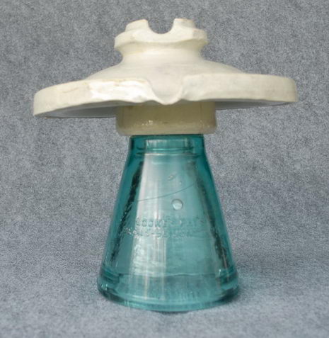
Only known white M-2795.
Power on the Bay Counties lines was started on April 27, 1901, even though construction was begun after work had started on the Standard Electric Co line. Water was turned into the main canal on February 8, 1902, which carried water to the Standard Electric Co. Electra Powerhouse. Power on the Standard Electric Co. line was started on May 6, 1902 from Electra. The five generators hummed with a total capacity of 10,000 kilowatts serving the Mother Lode area and the cities of Oakland and San Jose. Power was delivered to the 34 Kansas Street substation in San Francisco on November 3, 1902. A second line from Mission San Jose to San Francisco was completed in 1905, and the total voltage was raised to 60,000 volts. Additional generating units were installed at Electra to bring the plant's capacity to 20,000 kilowatts. The Electra plant was in continuous operation for nearly 50 years until it was replaced by a more modern Electra plant in 1948. The Prince stated that with "the somewhat forced liquidation of my interests in Standard Electric Company," he and his wife and sons returned to France in early 1903.
The first M-2795's were produced in about May 1900. Photographs taken of the Victor factory in June 1900 show about 18,000 porcelain top shells piled several feet high behind the testing lab. The earliest specimens were simply marked with Fred Locke's incuse marking #1-5 on one side of the porcelain top skirt and the word "VICTOR" on the other side. A couple of these earliest specimens have been reported with a large "303" above the word "VICTOR". Indeed, the June 1900 photograph, which shows the huge pile of porcelain top shells laying on the ground, clearly shows one insulator in the pile with the "303" marking. These were made just before the "Victor" styles (Nos. 300 to 319) were developed and announced in the August 1900 catalog No. 5. "303" was the initial catalog number, which was soon changed to "316" when the "Victor” series of styles was developed.
M-2796 (Locke catalog #318)
Production date: 1900-??
M-2842 and M-2842C (Locke catalog #323)
Production date: 1901

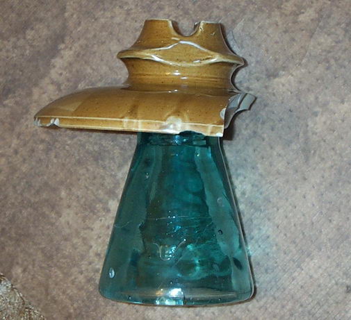
M-2842 were used on an unknown line in northern California related to the Bay Counties or Electra system. Like most of these 2-part designs, they were likely replaced and recycled on other lines. The majority of specimens were recycled and used on a line from the Gold Ray power house north through Grants Pass Oregon and were found in the early 1970's. Very few have also been found on later lines in PG&E territory in northern California. The larger crown version was produced first from the July 3, 1901 to September 23, 1901. The small crown style was initially produced from October 11 until November 22, 1901. All M-2842's are cemented with Portland cement and sand. There seems to be more specimens of the larger crown version. Only about four of the smaller crown style are known.
The large crown version of M-2842 is known with markings 4-3, 4-5, and 6-2. The small crown version is known with marking 6-2.
The glass base version is M-2842C and was cemented with sulfur. Only two damages specimens are known. Both were found in northern California in the 1970's. Details of these finds unfortunately have been lost. Both specimens have marking 6-2.
M-2842A and M-2842B
(Locke catalog #)
Production date:
M-2998 (Locke catalog #327)
Production date: 1902 only
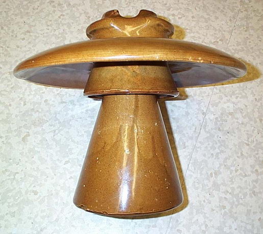
Narrow collar (left) and wider collar (right).
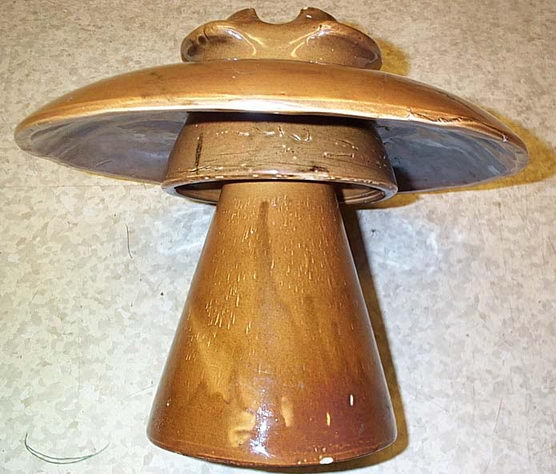
M-2998 was first shown in the 1902 catalog and later in the 1904 catalog. Only about 8 specimens are known and all have the #6-1 marking. One additional specimen has the same crown design as M-3725. There are three distinct varieties. Some have a wider collar under the top shell with a raised support ring as shown in photos above while others have a narrow collar similar to M-2785. A third variation has a narrow conductor groove and essentially uses a top skirt made using the same 2-part mold set as the early M-3725 with the wide collar skirt shown above. All have the collars glazewelded to the top skirt and all specimens are made in a 2-part mold.
Narrow collar (left) and wider collar (right) with support ring.
All of the M-2998 specimens were found in northern California on lines associated with the Pacific Gas & Electric and its predecessor companies. The major use of the M-2998 was as a replacement or upgrade for failing specimens of M-2795/M-2796 on the Bay Counties and Electra power lines. The M-2998's are known to have been installed extensively on the Colgate line in the foothills of the Sierras and throughout the Bay area in high fog areas in 1902. Because both of these lines were upgraded to 60 kV around 1904-06, all or nearly all M-2998's were removed from service. A large number were later reused on lines in the 23-33 kV range from 1904 to 1925. Often at locations where heavier strains existed the majority of known specimens have been found at locations where they were reused. The tops of these insulators are extremely fragile.
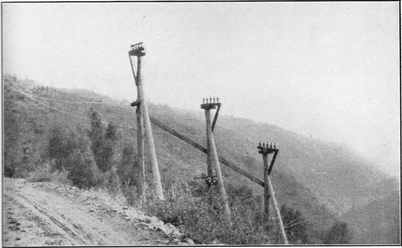
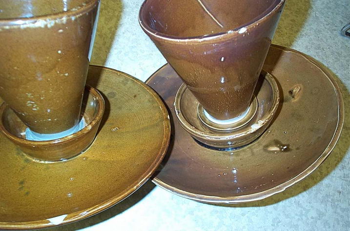
Pole on the De Sabla line in northern California with M-2998's.
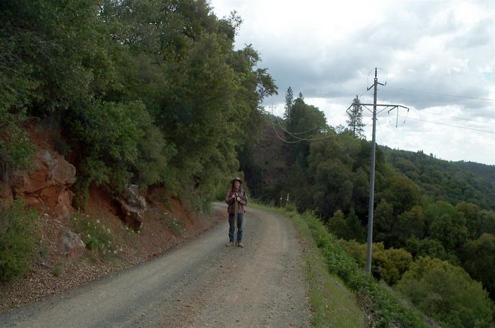
Mike Spadafora standing in the same location where the line crossed in previous photo.
Go to Multipart History Page 1 Page 2 Page 3 Page 4 Page 5 Page 6
Go to Main Page